

EcoPhi Gateway Nano
This manual explains how to install, connect, and configure the EcoPhi Gateway Nano. It covers hardware setup, Modbus RTU wiring, digital and analog inputs, internet connection options, and the Device Configurator interface.
1 Introduction
1.1 Description and Function of the EcoPhi Gateway Nano
The EcoPhi Gateway Nano connects Modbus RTU devices, digital sensors and analog sensors to the EcoPhi Platform. It supports Wi-Fi and GSM for internet connectivity.
1.2 Safety Instructions

The installation and operation of the EcoPhi Gateway Nano require compliance with basic safety regulations to ensure the safety of people and equipment:
Installation by qualified personnel: The Gateway Nano may only be installed and maintained by qualified personnel to avoid risks such as electric shocks or malfunctions.
Switch off the power supply: Before installation or maintenance, ensure that the power supply to the device is disconnected.
Use the components supplied: Only use the parts recommended or supplied by EcoPhi to ensure functionality and safety.
Seal cable glands: Open cable glands must be properly sealed before commissioning to prevent the ingress of moisture or foreign bodies.
1.2.1 Notes on Correct Cabling and Proper Connections

- Use shielded cables whenever possible.
- Ensure that there are no sources of interference near the cables, e.g., motor cables, power cables, or high-power cables.
- The greater the distance, the greater the influence of possible sources of interference.
- Make proper cable connections; do not use loose plug contacts or simple insulating tape.
- If necessary, remove the terminals supplied with EcoPhi sensors. They are intended only to demonstrate correct wiring, not for permanent use.
- If necessary, use the supplied heat-shrink tubing to extend and connect cables.
For serial devices: Avoid star connections; their maximum distance is 100 m. A 120 Ω resistor at the end of the connection improves transmission.
For pulse sensors: Avoid magnetic interference fields in the vicinity of pulse sensors, e.g., door sensors or water meters.
1.3 Glossary for the EcoPhi Gateway Nano
- DI (Digital Input): An input used to detect a digital state, for example from a door sensor.
- AI (Analog Input): An input used to measure voltage levels.
- 4–20 mA mode: Standard for analog signal transmission, often used with industrial sensors. The current range (4 to 20 mA) represents the measured value of the sensor.
- Modbus RTU: A serial communication protocol used to exchange data with connected devices over RS485.
- RS485: The serial interface used by the Gateway Nano for Modbus RTU communication.
- VCC (Voltage Common Collector): Supply voltage for sensors or other connected devices.
- GND (Ground): The electrical reference connection for the power supply or an interface.
- GSM: Mobile network communication used to connect the Gateway Nano to the internet.
- APN (Access Point Name): The network name required for the mobile connection to send and receive data via the mobile network.
- Nano SIM card: The form factor of the SIM card. It is the same form factor used in smartphones.
- Wi-Fi: Wireless network communication used to connect the Gateway Nano to the internet.
1.4 Data Consumption
The data consumption of the EcoPhi Gateway Nano depends largely on the connected devices, the frequency of data transfers, and the quality of the internet connection. While a stable connection reduces consumption, unstable connections can lead to higher data consumption through repeated data transmissions or connection attempts.
In a typical system with a moderate number of sensors and devices, the average monthly data consumption is around 200 MB. However, this value can vary considerably. Systems with more sensors or more frequent transmission intervals require correspondingly more data volume. Conversely, consumption can be reduced in systems with fewer data points or longer transmission intervals.
The Gateway Nano is designed to use data efficiently by transmitting only relevant data and minimizing unnecessary repetitions. This makes it suitable for systems that use mobile connections with limited data volumes.
1.5 Components of the EcoPhi Gateway Nano
1.5.1 Scope of Delivery
The Gateway Nano comes with:
- 1x Gateway Nano
- 1x casing
- 1x external GSM antenna
- 1x SIM card
- 1x power supply (optional)
1.5.2 Connections
The green 8-pin terminal block provides connections for the power supply, RS485 interface, and DI and AI inputs. The external GSM antenna connects to the designated SMA connector.
1.6 Tools Required for Installation
Have a suitable screwdriver available for connecting cables to the terminal block and, if required, for attaching the DIN rail mount.
2 Installation Instructions
2.1 Quick Guide
- Ensure that the Gateway Nano is powered down and have a suitable screwdriver ready.
- If required, attach the DIN rail mount and secure the Gateway Nano to a DIN rail.
- Plug the green 8-pin terminal block into the Gateway Nano before connecting the cables.
- For GSM connectivity, screw the supplied antenna onto the SMA connector and insert a nano SIM card while the Gateway Nano is powered down. No additional hardware setup is required for Wi-Fi.
- Connect the required interfaces: RS485 devices to
RS485A,RS485B,VCC, andGND; digital devices toDIandGND; and analog devices toAIas required. - Connect a 24 V / 2 A power supply to one
VCCand oneGNDterminal. The secondVCC/GNDpair can be used to supply connected devices. - Power on the Gateway Nano, connect to the Device Configurator, and configure Wi-Fi or SIM/APN settings. A GSM connection can take up to two minutes, depending on coverage.
- Check the connectivity status, then configure connected devices and their readouts in the EcoPhi Platform.
2.2 Preparations
Before beginning setup, ensure that the green 8-pin terminal block is plugged into the matching terminal on the device. This makes cabling easier and helps keep the installation process organized.
2.3 Internet Connectivity
The Gateway Nano supports Wi-Fi or GSM for internet connectivity.
2.3.1 Connection via GSM
Screw the provided GSM antenna onto the SMA connector.
If you wish to use your own SIM card instead of the supplied one, open the Gateway Nano casing and install the SIM card through the SIM installer hatch.
The Gateway Nano must be powered down while the SIM card is being installed. It will not recognize a SIM card inserted while it is running.
To configure the SIM interface, refer to Step-by-Step Setup.
2.3.2 Connection via Wi-Fi
No additional hardware setup is required for an internet connection via Wi-Fi.
To configure the Wi-Fi connection, refer to Step-by-Step Setup.
2.4 Cabling
This section explains the hardware setup of the available interfaces.
2.4.1 Power Supply
The terminal block has two pairs of VCC and GND terminals. Connect the recommended 24 V / 2 A power supply to one VCC and one GND power input terminal.
VCC and GND inputs are internally connected and the second pair can optionally be used as a power output for connected devices.
2.4.2 RS485/Modbus Interface
The RS485 interface has four pins (RS485A, RS485B, VCC, and GND) and enables the connection of RS485-capable devices.
2.4.3 Digital Input
The DI terminal can be used to connect a digital device, such as a door sensor. Connect the device’s input signal cable to DI and its corresponding ground cable to GND on the Gateway Nano. If the sensor has no polarity, connect DI and GND to either connection point on the device.
2.4.4 Analog Input
The AI pin can be used to connect an analog device, for example a current sensor.
2.5 DIN Rail Mounting
If required, attach the DIN rail mount to the designated attachment points and secure the Gateway Nano to a DIN rail.
3. Device Configurator
The Device Configurator is the local web interface used during on-site commissioning, service and support. It is intended for short-term local access to a device, for example to configure network settings, check connectivity and verify the latest readout state.
3.1 Typical Workflow
A typical installation follows this order:
-
Connect to the Device Configurator Wi-Fi.
-
Open the local web interface.
-
Sign in to the web interface.
-
Review or update login settings if required.
-
Check the current connectivity status.
-
Configure Wi-Fi access and connection priority.
-
Configure SIM/APN access and connection priority if mobile connectivity is used.
-
Review debug logs.
-
Check configured components and their latest readout state.
-
Stop the Device Configurator when the setup is finished.
3.2 Access Credentials
The Device Configurator Wi-Fi credentials and web-login credentials are separate. Use the credentials supplied for the individual device from the onboarding material.
3.2.1 Device Configurator Wi-Fi
SSID: Configurator <serial number>Password: <device-specific AP password>For an easy connection to the Device Configurator, use the supplied Wi-Fi QR code from the onboarding PDF. Alternatively, you can manually enter the password to connect to this Wi-Fi.
3.2.2 Local Web Login
Username: adminPassword: <web login password from onboarding PDF>If the web-login password was changed during a previous setup or service visit, use the changed password. The default password is the last five digits of the serial number.
3.3 Step-by-Step Setup
Step 1: Connect and Open the Web Interface
Connect your phone, tablet, or laptop to the Device Configurator Wi-Fi. After connecting successfully, operating systems often open the configuration page automatically. If the page does not open automatically, open this URL manually in a browser:
http://192.168.4.1/homeThe browser may show the local address as insecure. This is expected for a local setup portal without a public TLS certificate.
Step 2: Sign In
After opening the local page, log in with the web login
credentials supplied for the device in the onboarding PDF.
The username field is usually admin.
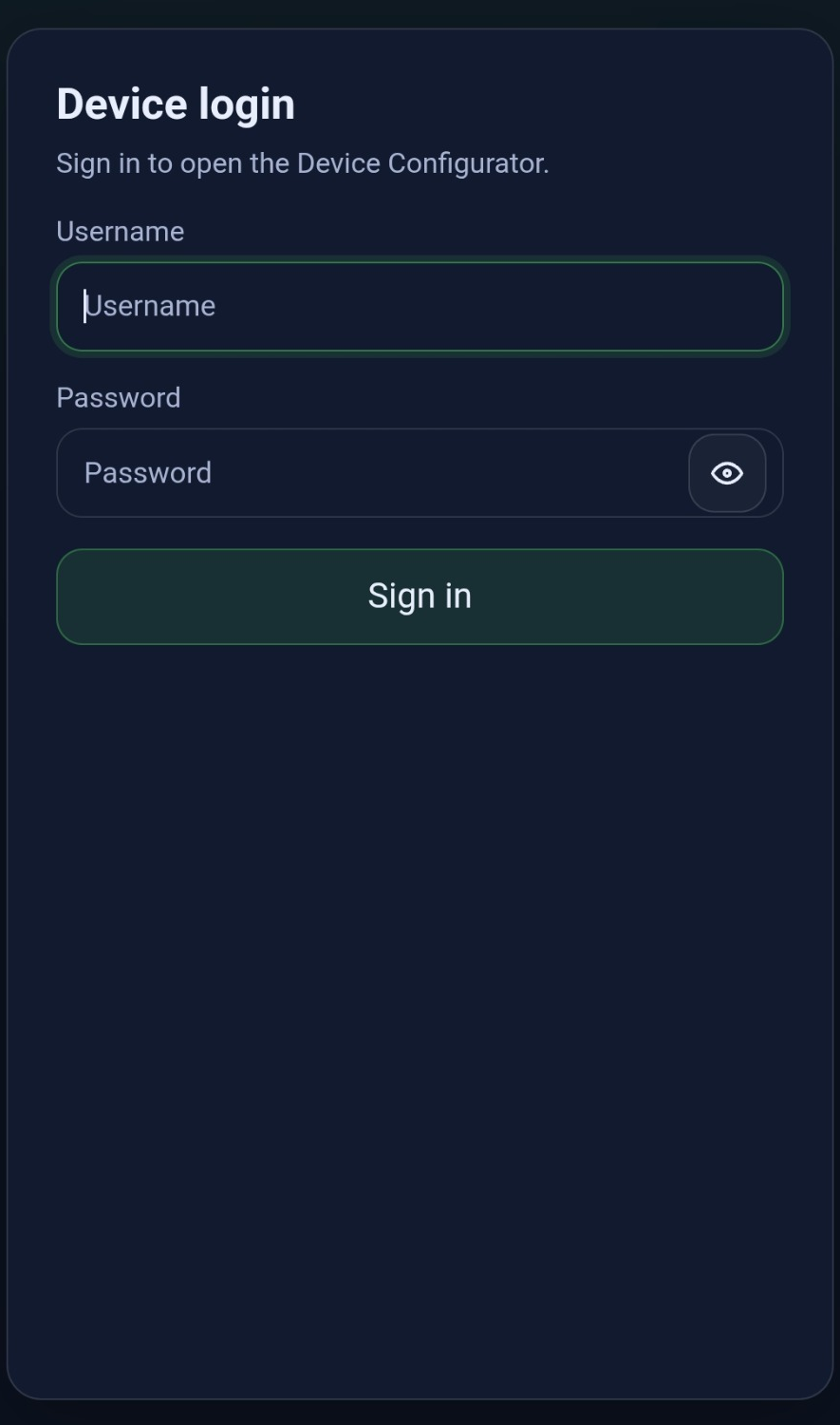
After a successful login, the session remains valid while you move between the configurator pages. This avoids repeated login prompts during the setup process.
Step 3: Use the Home Page
The Home page is the central navigation page. From here, you can open:
-
Connectivity status — current connection state and IP information.
-
Debug logs — simplified status messages.
-
Wi-Fi settings — Wi-Fi SSID, password, and connection order.
-
SIM settings — APN values and connection order.
-
Components — configured components and latest readout state stored on the device.
-
Login settings — web username and password settings.
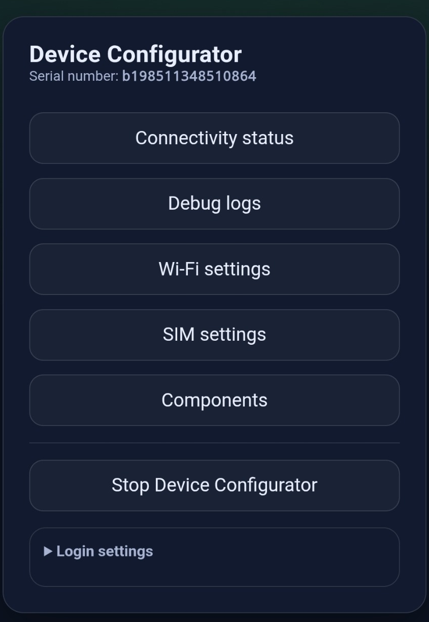
The Stop Device Configurator button is available on the Home page and the subpages. Use it only after setup and verification are complete.
Step 4: Optional: Review Login Settings
Open Login settings on the home page when you want to change the web login.
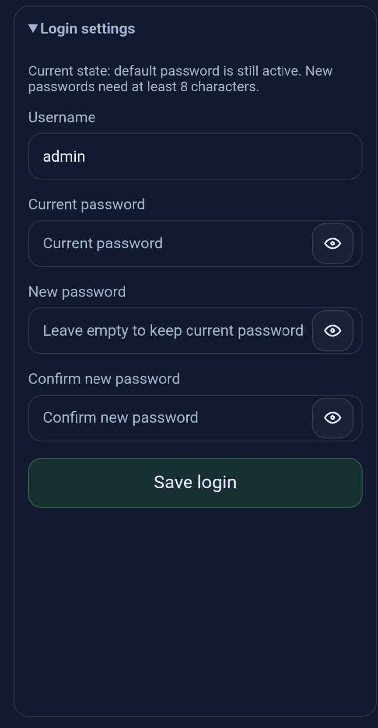
If the default password is still active, the interface indicates this state. To change it, enter the current password and the new password twice for confirmation and then save the login settings.
Step 5: Check Connectivity Status
Open Connectivity status to verify how the device is currently connected. Depending on the device and configuration, the page can show:
-
current connectivity state,
-
active transport, for example Wi-Fi or SIM,
-
active IP address,
-
connected and configured Wi-Fi SSID,
-
mobile network details if available,
-
Device Configurator IP and connected client count,
-
AWS/MQTT connectivity state (Connection to EcoPhi Portal Backend).
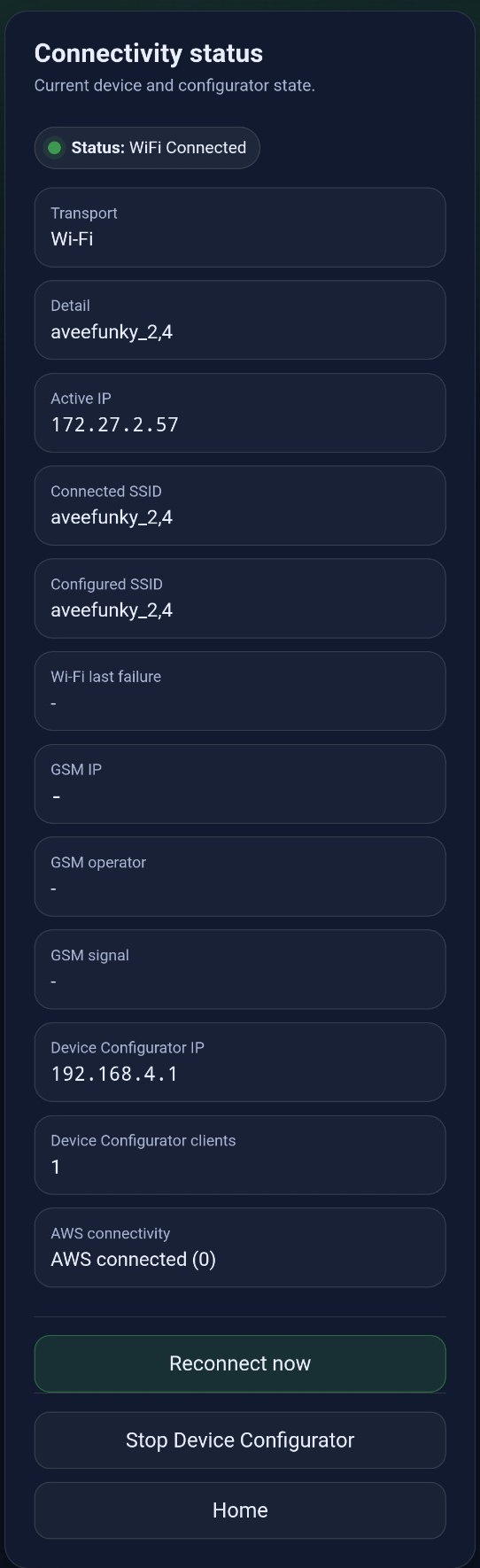
Use Reconnect now if a manual reconnect is required after changing network parameters or when troubleshooting connectivity.
Step 6: Configure Wi-Fi
Open Wi-Fi settings to save or update Wi-Fi credentials. The page supports keeping the current network, selecting or entering a new SSID, entering a password, clearing stored Wi-Fi data and choosing the connection order.
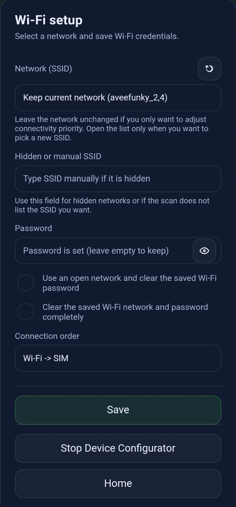
The visible connection order values are:
-
Wi-Fi -> SIM -
SIM -> Wi-Fi
Choose Wi-Fi -> SIM when Wi-Fi should be the primary connection and
SIM should be used as fallback. Choose SIM -> Wi-Fi when mobile
connectivity should be preferred.
Press Save after changing values. After saving, check Connectivity status again and use Reconnect now if required.
Step 7: Configure SIM and APN Settings
Open SIM settings to configure APN values and the connection order for mobile connectivity. Depending on the SIM provider, APN user and APN password may be optional.
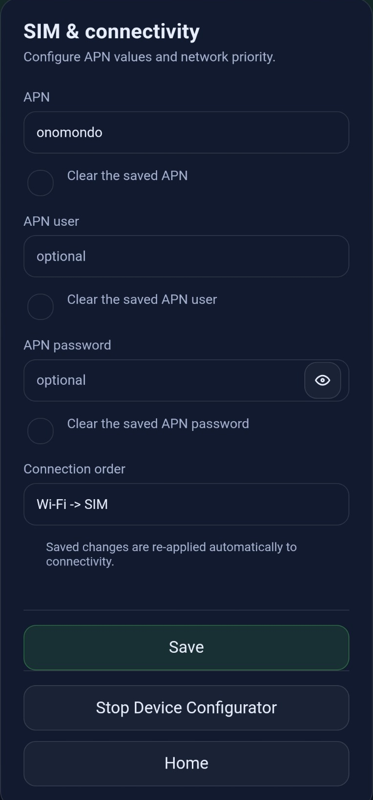
Each APN field can be cleared individually. This is useful when a provider changes from authenticated APN access to unauthenticated APN access, or when incorrect values were stored previously.
After saving SIM settings, return to Connectivity status to verify that the device can connect as expected.
Step 8: Review Debug Logs
Open Debug logs during installation or support calls to see status messages. The page focuses on customer-relevant events such as:
-
attempts to connect to the internet via Wi-Fi or mobile network,
-
connection successes and failures,
-
connection losses,
-
component readout attempts,
-
successful or failed readouts,
-
data sent to the cloud.
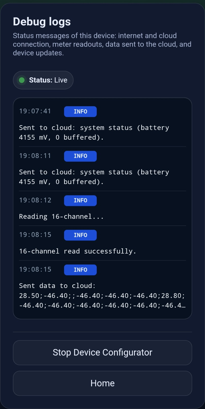
The messages are loaded only after login and are updated while the page is open.
Step 9: Check Components and Latest Readout State
Open Components to verify the locally configured components with their latest cached readout state and values. Components are added, configured and deleted in the site settings in the EcoPhi Portal. Use the portal URL from the onboarding PDF or your email inbox. The Gateway Nano must have an active internet connection to receive component changes.
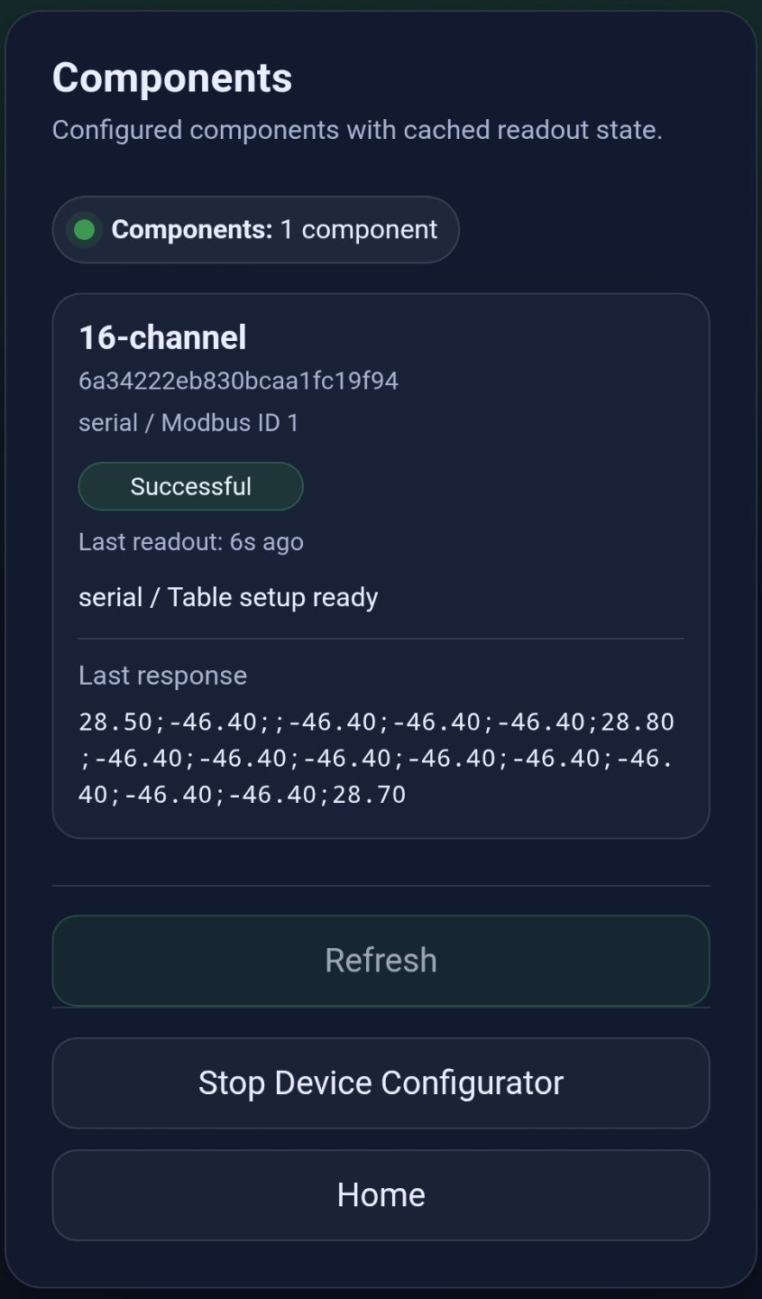
For each component, the page can show:
-
the component name or type,
-
the component ID,
-
protocol or Modbus ID information,
-
table setup status,
-
whether a readout has already been attempted,
-
whether the latest readout was successful or failed,
-
the time since the latest readout attempt,
-
latest readout state and values stored on the device.
The page refreshes automatically every two seconds to keep the visible state up to date. Use Refresh to update the state manually.
Step 10: Stop the Device Configurator
When installation and verification are complete, press Stop Device Configurator. The interface asks for confirmation before shutting down the configurator.
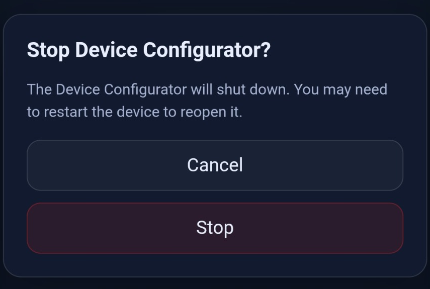
Confirm only when you no longer need local access. After stopping, you may need to restart the device to open the Device Configurator again.
3.4 Troubleshooting Checklist
| Issue | Recommended check |
|---|---|
| The web page does not open | Confirm that the phone or laptop is connected to the Device Configurator Wi-Fi. Then open http://192.168.4.1/home manually. |
| Device Configurator Wi-Fi connection fails | Use the device-specific AP password from the onboarding material, printed label, or QR code. If the supplied credentials do not work, contact support and provide the device serial number. |
| Login fails | Check the supplied web login password for this device. If the password was changed previously, use the changed password. |
| Gateway does not connect to Wi-Fi | Check SSID spelling, network password, hidden SSID settings, and connection order. Save again and use Reconnect now. |
| SIM does not connect | Check the APN, APN user, and APN password with the SIM provider. Clear fields that should be empty. |
| Cloud connectivity is missing | First verify the local transport and IP address. Then check the AWS/MQTT status on the Connectivity status page. |
| No readout values are shown | Open the Components page and check whether the component is configured, whether a readout has been attempted, and whether the latest readout was successful. |
| The configurator disappeared | The Device Configurator may have been stopped or may have shut down automatically, depending on the firmware configuration. Restart the device if local setup access is required again. |
4. FAQ
This section provides answers to frequently asked questions.
| Question | Answer |
|---|---|
| What power supply does the Gateway Nano require? | Use a 24 V / 2 A (48 W) power supply connected to one VCC and one GND terminal. A lower-rated power supply can cause unstable GSM communication or slow gateway performance. |
| Can I use my own SIM card? | Yes. Install a nano SIM card through the SIM installer hatch while the Gateway Nano is powered down. |
| Why is my new SIM card not recognized? | The Gateway Nano does not recognize a SIM card that was inserted while it was running. Power it down before installing the SIM card. |
| How long does a GSM connection take? | Depending on local GSM coverage, it can take up to two minutes. |
| Do the Device Configurator Wi-Fi and web login use the same password? | No. The Wi-Fi and web login credentials are separate. |
| There was a network outage. When can I see the restored data on the EcoPhi Platform? | The Gateway Nano resends data after a network outage in chunks. It can take up to 30 minutes for data to become visible on your dashboard. |
| My Wi-Fi is not shown in the search list despite being in range. Why? | Check the frequency band of your Wi-Fi router. The Gateway Nano supports only the 2.4 GHz band. |
| My Modbus device is being read out, but the values do not seem plausible. What should I check? | Check the cabling of the RS485 interface. The RS485A and RS485B cables are often switched, which can lead to false readings. |
5. Support and Further Information
If you encounter problems with the EcoPhi Gateway Nano during installation, configuration, or operation, our support team will be happy to help.
Please create a ticket via our online ticket system: https://ecophi.io/support-request/
Our team will get back to you promptly with a solution or further instructions.
EcoPhi Renewables Engineering GmbH
Alter Schlachthof 33
76131 Karlsruhe
www.ecophi.io