EcoPhi Plant Controller/ Plant Monitor
You can also find our video tutorials here: https://www.youtube.com/@EcoPhiRenewables
1 Introduction
1.1 Description and function of the EcoPhi Plant Controller
The EcoPhi Plant Controller is a modern communication edge device that has been specially developed for the requirements of renewable energy systems. The device enables the monitoring and control of serial devices, sensors and actuators and provides a central platform for data processing.
The Plant Controller was developed by EcoPhi, a company specializing in innovative IoT solutions for renewable energy. EcoPhi focuses on providing efficient and robust technologies that enable customers to optimally operate and monitor their systems. The Plant Controller plays an important part in this offering, as it ensures reliable data collection and a stable connection to the EcoPhi Cloud.
The EcoPhi Plant Controller is a central component of modern energy systems that combines several essential functions. It was developed to collect data from connected external devices and sensors, process it locally and make it accessible via a cloud platform. The Plant Controller is not only used to collect data, but also to control devices in renewable energy systems.
In addition to data acquisition, the Plant Controller can also send control commands to connected devices. This includes, for example, the control of inverters, battery systems or generators, giving it an active role in energy management. Integration into the EcoPhi Cloud extends the functions to include remote monitoring and control, enabling operators to efficiently manage their systems remotely.
The Plant Controller is therefore more than a simple data logger - it is an intelligent communication device that links data and control commands in one system and creates the basis for effective energy management.
1.2 Safety instructions
The installation and operation of the EcoPhi Plant Controller requires compliance with basic safety regulations to ensure the safety of persons and equipment:
Installation by qualified personnel: The Plant Controller may only be installed and maintained by qualified specialist personnel in order to avoid risks such as electric shocks or malfunctions.
Switch off the power supply: Before installation or maintenance, ensure that the power supply to the device is disconnected.
Use the components supplied: Only use the parts recommended or supplied by EcoPhi to ensure functionality and safety.
Seal cable glands: Open cable glands must be properly sealed before commissioning to prevent the ingress of moisture or foreign bodies.
Notes on correct cabling and proper connections

- It is strongly recommended to use shielded cables.
- Ensure that there are no sources of interference near the cables, e.g. motor cables, power cables, high-power cables.
- The greater the distances, the greater the influence of possible sources of interference
- Connect cables properly and not via loose plug contacts or simple insulating tape.
- If necessary, remove the supplied terminals from sensors supplied by EcoPhi, as they are not intended for permanent use, but only to show that the wiring is correct.
- If necessary, use the heat-shrink tubing supplied to extend and connect the cables.
For serial devices: Avoid star connections; the maximum distance for star connections is 100 m. A 120 Ohm resistor at the end of the connections improves transmission.
For pulse sensors: Avoid magnetic interference fields in the vicinity of pulse sensors, e.g. door sensors or water meters.
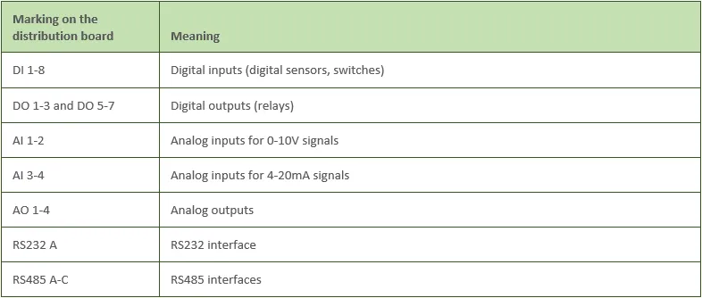
1.3 Glossary for the EcoPhi Plant Controller
- 2FF (Mini SIM): A specific SIM card format that is used with the EcoPhi Plant Controller.
- 4-20mA mode: Standard for analog signal transmission, often used with industrial sensors. The current range (4 to 20 mA) represents the measured value of the sensor.
- AI (Analog Input): Analog inputs that can detect changing states of sensors, usually through a sensor signal of 0-10V or 4-20mA.
- AO (Analog Output): Analog outputs that send signals to external devices.
- APN (Access Point Name): Network name that is required for the mobile connection to send and receive data via the mobile network.
- Bar chart: Visualization on the Plant Controller display that graphically shows the current value of an analog sensor.
- CSV (Comma-Separated Values): A file format used in the Plant Controller to save or import configurations and settings.
- DI (Digital Input): Digital inputs that can recognize binary states (on/off) of sensors or switches.
- DO (Digital Output): Digital outputs that send signals (on/off) to external devices such as relays or contactors.
- Ethernet: Wired network interface used for a stable connection and data transmission.
- GND (Ground): Earthing point in the Plant Controller that is important for the safe connection with other devices.
- Modbus: A communication protocol used in the Plant Controller to communicate with devices such as inverters or sensors via RS485 or TCP/IP.
- RS232: A standard for serial communication used in the Plant Controller for certain devices.
- RS485: A serial communication protocol that is often used in industrial applications. The Plant Controller supports it for connection to sensors and other devices.
- SD card: A storage medium used in the Plant Controller for data backup and configuration updates.
- SNR (Signal-to-Noise Ratio): Ratio of signal strength to noise, which describes the quality of a radio connection.
- SSID (Service Set Identifier): Name of a WLAN network that is required for the WiFi connection of the Plant Controller.
- VCC (Voltage Common Collector): Supply voltage for sensors or other connected devices.
- WiFi: Wireless network interface of the Plant Controller, which is used to connect to the EcoPhi Cloud or local networks.
1.4 Technical data
1.4.1 Power consumption
Under maximum load, the Plant Controller can consume up to 30 watts. This maximum power consumption typically occurs during intensive use, for example when numerous devices are connected or when a high data transfer rate is required.
In normal operation, however, the average power consumption of the plant controller is around 3 to 4 watts. This value varies depending on the number and type of sensors connected, the frequency of data transmission and the communication interfaces used, such as WiFi or Ethernet. The use of the integrated touchscreen can also increase power consumption.
The low average power consumption of the Plant Controller also makes it suitable for applications in energy-efficient systems, where minimizing power consumption is of central importance.
The EcoPhi Plant Controller requires a reliable power supply for operation, which is provided via 230V AC as standard. The incoming AC voltage is converted into 24V DC via an integrated AC/DC converter, which supplies the Plant Controller and the connected devices with energy.
Maximum power consumption: The Plant Controller has a maximum power consumption of 1.25A under full load, depending on the number and type of sensors and outputs connected. In normal operation, consumption is significantly lower, meaning that the device works efficiently and economically.
Emergency power supply: The Plant Controller is equipped with an internal battery that keeps the data logger operational for up to 4-5 hours even in the event of a power failure. This backup power solution ensures that important data continues to be stored and that there is no interruption in communication with the platform as soon as the main power supply is restored.
Alternative power supply: It is also possible to use your own or an alternative power supply. However, this must be compatible with the connected devices and be able to supply a voltage between 11.5V and 30V DC. Stable operation of the Plant Controller is only guaranteed if these specifications are met. A minimum supply of 14 VDC is required for the configuration of the 0-10 V analog output.
1.4.2 Data consumption
The data consumption of the EcoPhi Plant Controller depends largely on the connected devices, the frequency of data transfers and the quality of the internet connection. While a stable connection reduces consumption, unstable connections can lead to higher data consumption due to repeated or repeated connection attempts.
In a typical system comprising a moderate number of sensors and devices, the average monthly data consumption is around 200 MB. However, this value can vary considerably. Systems with a higher number of sensors or more frequent transmission intervals require correspondingly more data volume. Conversely, consumption can be reduced for systems with fewer data points or longer transmission intervals.
The Plant Controller is therefore designed to keep data consumption efficient by only transmitting relevant data and minimizing unnecessary repetitions. This also makes it suitable for systems that rely on mobile connections with limited data volumes.
1.5 Components of the EcoPhi Plant Controller
1.5.1 Scope of delivery
In addition to the EcoPhi Plant Controller, the following components are supplied as standard:
- Key for opening the housing
- Mains cable with switch
- 2-, 3- and 4-pin connector for connection to the distribution board
- Heat-shrink tubing for simpler and tidier cabling
- Cable glands, consisting of gland, nut, rubber ring and plug
- Brackets and screws for attaching the Plant Controller to the wall
1.5.2 Internal components of the Plant Controller
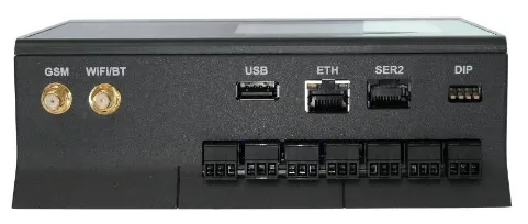
The EcoPhi Plant Controller consists of several key components housed in a robust casing.
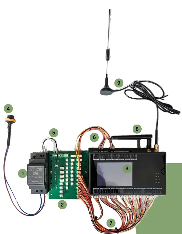
1 Power supply: An integrated power supply unit ensures that all Plant Controller components are reliably supplied with power.
2 Distribution board: The distribution board was developed to simplify the connection of external devices, sensors and actuators. It offers a simple connection option, simplifies cabling and ensures a clear structure during installation.
3 Data logger/main unit: This is the heart of the Plant Controller, which is responsible for processing and storing the data collected by the external device sensors. It also handles communication with the EcoPhi Cloud and other connected devices as well as the control logic.
4 Power supply cable: This cable is integrated into the housing of the Plant Controller. The Plant Controller can be supplied with a voltage of 230 V AC via the power supply cable included in the scope of delivery.
5, 6, 7 Internal cabling: These cables are used for data and signal transmission and power supply and must not be modified without consulting EcoPhi.
8 Wifi antenna: The Wifi antenna enables a connection to be established to a local Wifi network.
9 GSM antenna: The GSM antenna can normally remain inside the housing and still establish a sufficient connection. However, it can also be routed through the housing to the outside if the connection is too weak.
Housing with switch cabinet and door: All of the above components are housed in a robust control cabinet that offers protection against dust, moisture and mechanical influences. The door allows easy access to the internal components and can be locked for safety.
1.5.3 The data logger/main unit
The data logger/main unit is the heart of the Plant Controller. There is a large LCD display with touchscreen on the front of the device, which shows the detailed status of the device. Detailed information on the LCD display with touchscreen can be found in the section Detailed information on the LCD display. The user and system LEDs and the reset switch are also located on the front of the device.
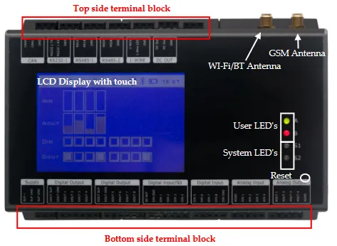
1.5.4 Display
The display of the data logger is a white-blue graphic display with a resolution of 240x160 pixels and a built-in resistive touch sensor.
A range of display functions are available for the graphical and alphanumeric display of data, user interaction with menus, etc.
By default, the display is switched on at startup and shows the I/O status, the battery status and the status of the communication interfaces, as shown in the following illustration.
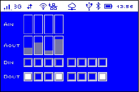 The status of the various inputs and outputs is shown in the main part of the display.
At the top, the analog inputs (AIN) and outputs (AOUT) are displayed with bar charts to show the current value (from left to right AI1 - AI4 and AO1 - AO4).
Below the analog values, the digital inputs (DI) and outputs (DO) are displayed in groups of 4.
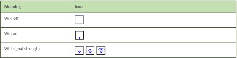
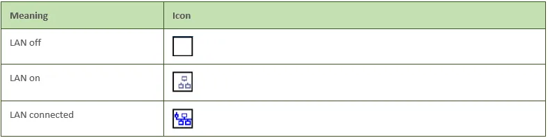
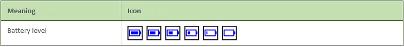
The upper area shows the status bar, which displays the status of the various communication interfaces as well as the time and battery status.
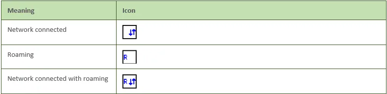
The relevant icons in the status bar are:
GSM status
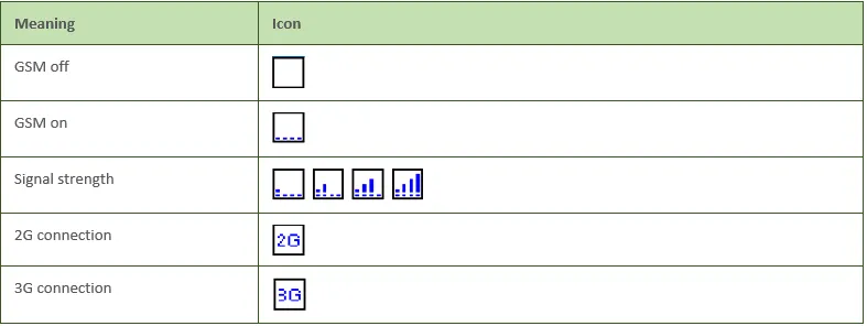
Mobile network status
WiFi status
LAN status
Power status
1.5.5 LED lights for recognizing the device status
The EcoPhi Plant Controller provides visual feedback via various LEDs that indicate the status of the device and the connection. These displays are important for quickly identifying and rectifying problems.
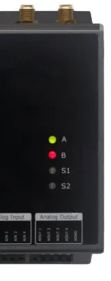
LED A: Internet connection
LED A indicates the status of the Internet connection. The colors and flashing patterns have the following meanings:
Color assignment of LED A:
Flashing and lighting behavior of LED A:
LED B: No relevant standard information, reserved for individual adjustments
This LED is only relevant if an individual flashing pattern has been programmed for your specific application.
LED S1: General operating status
The system LED1 indicates the general status of the EcoPhi Plant Controller. The different flashing patterns and colors have the following meanings:
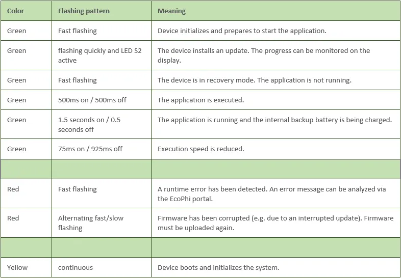
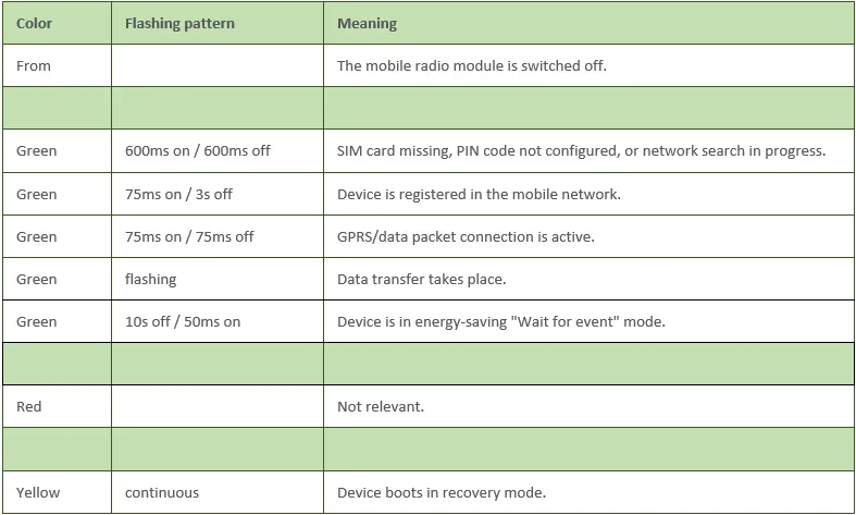
LED S2: Mobile radio activity and “Waiting for event”
The system LED2 provides information about the mobile phone connection and the operating status:
These LED indicators enable quick and easy diagnosis of the operating and connection statuses. In the event of a fault, they can provide important information for troubleshooting.
1.5.6 The distribution board
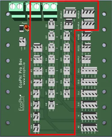
Connect the external devices, sensors or actuators to the distribution board using the 2, 3 or 4-pin connectors supplied. Use the marked and labeled pins on the distribution board. Observe the following pin assignment:
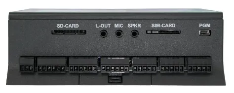
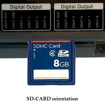
1.5.7 SD card
The EcoPhi Plant Controller has an SD card that performs several functions:
Intermediate storage of data: The SD card serves as a buffer when no internet connection is available. All data collected during offline time is stored on the SD card and automatically transferred to the EcoPhi Cloud later.
Saving images: If a camera is connected to the Plant Controller, the recorded images are saved directly to the SD card.
Configuration via SD card: The SD card can be used to save configuration files and transfer them to the Plant Controller. This is particularly useful if the device is installed in a remote location and the settings cannot be changed via the platform.
The EcoPhi Plant Controller is supplied with an SD card as standard. To insert a card, align it as shown below and press the card into the card slot until you hear a click. Remove the card by pushing it deep into the slot until it clicks into place and is ejected. Avoid removing the SD card at all costs while accessing the card.
1.6 Tools required for installation
The following tools and aids are required to install the EcoPhi Plant Controller:
- Electric screwdriver (slotted): For connecting the cables to the distribution board
- Material for cable connection: For example, cable clamps, heat-shrink tubing or soldering materials.
- Hot air dryer or lighter: For shrinking heat-shrink tubing to insulate the connections.
- Cordless drill: For wall mounting of the Plant Controller or installation in a control cabinet.
2 Installation instructions
2.1 Quick Guide
This checklist will help you to carry out the installation of the EcoPhi Plant Controller in a structured manner. Please work through the points in order.
Preparation
- Make sure you have access to the EcoPhi Cloud platform.
- Select a suitable location that is easily accessible, offers reliable network coverage (mobile radio, WLAN or LAN) and enables the shortest possible sensor cables.
- Have the necessary tools ready, such as electric screwdriver, cordless drill, cable clamps and hot air gun.
- Check the scope of delivery of the Plant Controller, including power supply unit, connection cable, GSM and WiFi antenna as well as the supplied cables and cable glands.
Mechanical installation
- Attach the Plant Controller securely to the wall by mounting the housing with screws and wall plugs.
- Attach the cable glands and seal unused openings to protect the device from dust and moisture.
Electrical connections
- Connect the power supply and check the function using the LED activity.
- Set up the Internet connection via Ethernet, WiFi or SIM card.
- Wire sensors and actuators according to the requirements. Ensure that digital and analog inputs/outputs are assigned correctly and that the analog input types are set correctly (0-10V and 4-20mA).
- With RS485 cables, make sure that there are no external sources of interference in the vicinity to avoid signal interference.
- Connect RS485/RS232 devices and ensure that the A/B lines are not reversed.
Commissioning
- Connect the EcoPhi Plant Controller to the EcoPhi Cloud by registering the device in the platform and configuring the connected sensors in the “Site Settings”.
- Check the connection status using LED “A” and ensure that the network connection is stable.
Final check
- Check that all cables are firmly connected and correctly insulated.
- Make sure that there are no unused openings in the housing.
- Make sure that the Plant Controller is running stably and does not display any error messages or unusual LED displays.
2.2 Preparations
2.2.1 Access to the EcoPhi portal
User account: To be able to connect the EcoPhi Plant Controller, you need a registered user account and an associated entity at www.portal.ecophi.io. If no account exists, you can find more information on registration in the platform manual.
Create device as data source:
Log in to the platform.
Select an existing site or create a new one.
Add the Plant Controller as a data source by entering the device ID (e.g. m315******). This ID can be found on the side of the box.
Configure site settings:
Specific settings for the Plant Controller can be made in the Site Settings.
Components such as sensors or actuators that are connected to the Plant Controller can also be created here.
2.2.2 Preparations on the box
A few preparatory steps are necessary before starting the cabling:
Remove packaging material:
Remove all packaging material that is still inside the appliance to ensure correct operation.
Attach cable glands:
The housing is supplied with open holes to allow flexible cable routing. Screw the required cable glands firmly into the corresponding openings to ensure a secure and weatherproof seal.
Close any unused openings:
Seal all unused holes and feed-throughs with the plugs supplied. This protects the Plant Controller from moisture, dust and other environmental influences.
2.3 Connection with the EcoPhi Cloud
The EcoPhi Plant Controller communicates with the EcoPhi Cloud platform. This platform enables configuration of the device, management of the data and integration with other systems. Most settings are made directly on the platform and only in exceptional cases directly on the device. A stable internet connection must therefore be set up first.
2.3.1 Connection options
The EcoPhi Plant Controller offers three options for establishing an internet connection: Ethernet cable, SIM card and WiFi.
If multiple connection types are available, the device automatically selects the first working connection. This prioritization order (Connection Order) can be adjusted via the online portal if required.
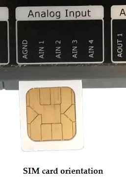
2.3.1.1 Connection via SIM card
One of the simplest and most flexible methods of connecting The Plant Controller to the Internet is to use a SIM card. This method allows connection via the mobile network and is particularly suitable for locations without wired Internet access.
Inserting the SIM card:
Before the Plant Controller can establish a connection, a compatible SIM card must be inserted into the corresponding slot.
Insert the card into the SIM slot as shown in the illustration and make sure that it is correctly aligned as shown in the pictures below. The card should be able to be inserted without force and make a clearly audible “click” sound when it clicks into place.
Be particularly careful, as the SIM card may be pushed past the holder on the Plant Controller and fall into the housing.
A mechanical slide lock can also be used to prevent the card from being accidentally removed.
To remove the card, slide the lock to the unlocked position and push the card into the reader until you hear a soft click. The reader will now eject the card. You may need to use a small tool or pencil to push the card into the reader.
Configure the APN settings:
With some mobile phone providers, additional APN settings must be made in order to establish a connection. This can be done in two different ways:
By SMS:
Send a message with the following content to the SIM card number:
Message structure: apn:apn_name;apn_user;apn_password
(Example: apn:internet.t-mobile;user;password)
Via SD card:
Place a CSV file with the name command.csv with the APN settings in the main folder of the SD card. The file must have the following structure:
File content: apn:apn_name;apn_user;apn_password
(Example: apn:internet.t-mobile;user;password)
2.3.1.2 Connection via Wifi
The EcoPhi Plant Controller can also be connected to the internet via a WiFi network. This method is particularly suitable for locations where stable WiFi is available.
The WiFi settings can be configured in several ways:
Setup via the EcoPhi platform:
Log in to the platform and navigate to the Site Settings. Here you can enter the network (SSID) and password to configure the connection.
By SMS: If you have a mobile connection, you can also adjust the WiFi settings via SMS. To do this, send a message in the following format to the SIM card number:
Message content: wun:WiFi_name(SSID);WiFi_Password
(Example: wun:HomeNetwork;securepassword123)
2.3.1.3 Connection via Ethernet
The most stable method of connecting to the Internet is to use an Ethernet cable. This method is recommended if wired Internet access is available.
Connect the Plant Controller to a network router or switch by feeding an Ethernet cable through the marked large cable entry into the box and plugging it into the “ETH” connection of the device.
Check the LED “A” next to the connection:
- Flashing green: Connection active.
- Red: No connection.
Automatic connection: If the connection is not established immediately, the Plant Controller automatically attempts to establish a connection every 10 minutes. Alternatively, the device can be restarted manually to speed up the process.
2.3.2 Changing the Internet settings when no Internet is available
If the Plant Controller cannot connect to the Internet, there are several alternatives for changing the settings manually. Each method is tailored to different situations and requires specific steps:
By SMS
If a SIM card is installed in the device, the settings can be changed by sending an SMS. To do this, send a message with the desired changes to the phone number of the SIM card used.
Examples of SMS commands:
"status": Returns the current connection status.
"restart": Restarts the device.
"apn:apn_name;apn_user;apn_password": Sets the APN settings. (Example: apn:internet.t-mobile;user;password)
"wun:WiFi_name(SSID);WiFi_Password": Changes the WiFi settings. (Example: wun:HomeNetwork;securepassword123)
Use of a hotspot
If no permanent Wi-Fi is available, a smartphone can be used as a temporary hotspot. This is particularly useful for tests or short-term connections during commissioning.
Use the following settings:
Network name: aveefunky_2,4
Password: funky2015avee2019
Per EcoPhi Portal
To temporarily connect to the EcoPhi portal, you can create a hotspot. If the device can be successfully connected to the EcoPhi platform in the short term, Internet settings can be adjusted via the portal:
Log in to https://portal.ecophi.io.
Navigate to the “Site Settings”.
Adjust the required settings for the device.
Via SD card
Another way to change the settings is to use an SD card.
Create a CSV file with the file name command.csv and the required settings. Message structure:
apn:internet.t-mobile;user;password: Sets the APN settings.
wun:HomeNetwork;securepassword123: Sets the WiFi settings.
Save the file in the root directory of the SD card.
Insert the SD card into the Plant Controller and restart the device. The Plant Controller automatically adopts the new settings.
2.3.3 Meaning of the LED lights on the controller/main unit
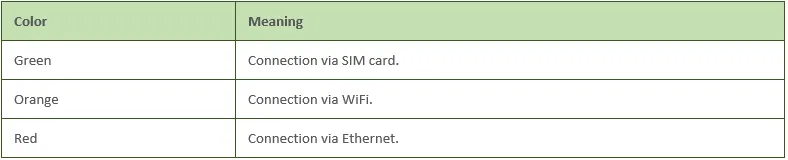
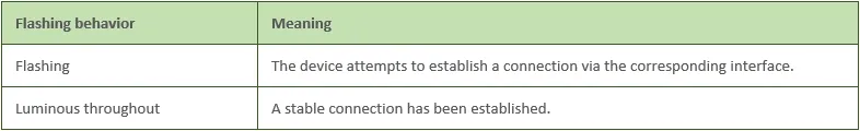
The LED “A” on the Plant Controller is a key tool for monitoring the status of the Internet connection. It not only shows the type of connection, but also its status. This visual display helps to identify the status of the Internet connection and to take appropriate measures to rectify faults if necessary.
The different colors and states have the following meanings:
Color assignment of LED “A”:
Flashing and lighting behavior of LED “A”:
Examples:
LED “A” Flashing green: The Plant Controller is trying to establish a connection via the SIM card.
LED “A” solid orange: The connection via WiFi has been successfully established.
LED “A” Flashing red: The device is trying to establish a connection via Ethernet.
2.3.4 Antennas
The EcoPhi Plant Controller is equipped with a GSM antenna (for the mobile phone connection) and a WiFi antenna as standard. These antennas enable reliable data communication and are crucial for the connection to the EcoPhi Cloud.
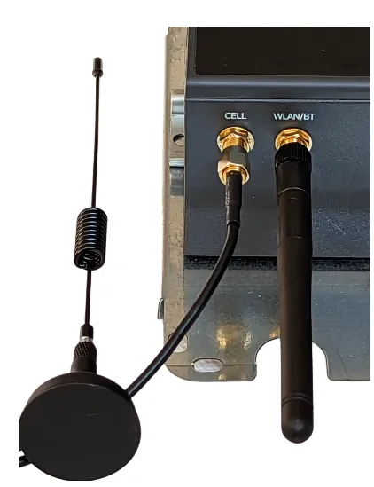
Standard operation of the antennas: The antennas are installed in the device and work reliably inside the housing in most cases. However, if the connection is impaired by metallic shielding (e.g. by a metal housing or walls), it may be necessary to route the antennas to the outside.
Signal display: The reception of the antennas can be viewed directly via the display. The signal strength and quality of the connection can be checked here. This helps to identify problems and enables targeted optimization of the antenna alignment.
Improve signal reception: If the signal quality is insufficient or connection dropouts occur, it is advisable to move the antennas to the outside. The Plant Controller stores unsent data for up to several months and transmits it automatically as soon as the connection is re-established. This means that no important information is lost.
2.4 Cabling
This chapter describes how to wire the EcoPhi Plant Controller. As the connections can vary greatly depending on the application, you will find general guidelines, specific instructions and technical details on the connections here.
2.4.1 Circuit diagram of the distribution board
Various devices and sensors can be connected to the distribution board of the EcoPhi Plant Controller. Please refer to the following diagram for the exact pin assignment and connections. This circuit diagram shows which connections are intended for which device types.
Connect the external devices, sensors or actuators to the distribution board using the 2, 3 or 4-pin connectors supplied. Use the marked and labeled pins on the distribution board. Observe the following pin assignment:
The wiring diagram helps you to identify the correct connections for your specific applications.
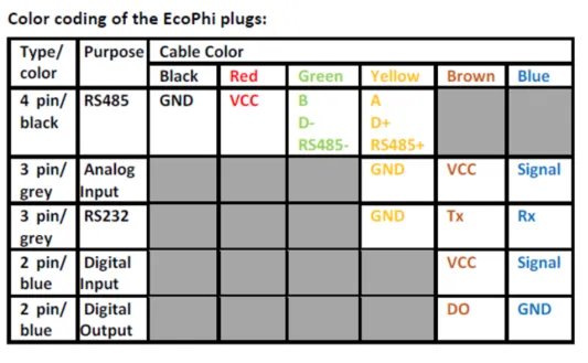
2.4.2 Color coding of the EcoPhi connection cable
Use the supplied connection cables with the 2.3 and 4-pin connectors to connect external devices or sensors to the distribution board of the Plant Controller. Take the following color codes into account:
2.4.3 Connecting external devices and sensors
Use the 2, 3 or 4 PIN connectors supplied for connection. Connect these to the sensor or external device according to the sensor or device specification, guide the cable end with the PIN connector through one of the openings in the housing and plug the PIN connector into the corresponding slot on the distribution board. The Plant Controller supports a large number of external devices, sensors and actuators. Depending on the type, these are wired as follows:
2.4.3.1 Digital inputs (DI1-DI8)
The digital inputs work with two pins (VCC and signal) and are designed as wet contact inputs (24V). They can be used for simple switching states (“On/Off”) as well as for pulse counting.
Pulse counting: The maximum counting frequency is 10 kHz.
Live display: The Plant Controller display shows the status of each digital input as “On” (white) or “Off” (blue). This helps to quickly check the wiring.
2.4.3.2 Digital outputs (DO1-DO8)
The digital outputs consist of two pins (signal and GND) and work with wet contact signals (24V).
Maximum load: Up to 1A current and 20mH inductance.
Application: For controlling devices such as relays or contactors.
Live display: The Plant Controller display shows the status of each digital output as “On” (white) or “Off” (blue) regardless of the platform settings. This helps to quickly check the wiring.
2.4.3.3 Analog inputs (AI1-AI4)
Analog inputs work with three pins (VCC, GND, signal) and support two modes:
- 0-10V mode: For voltage output sensors
- 4-20mA mode: For current output sensors
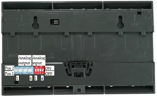
Changing the modes for analog inputs
It is possible to switch between modes using the red dip switch on the back of the Plant Controller.
To do this, you must first remove the data logger/main unit from the DIN rail. To do this, pull the pre-wired connector under “Digital Input/S0” out of the data logger to expose the opener. Use a slotted screwdriver to push the opener forwards and lift the data logger upwards at the same time. Now turn the data logger over. Do not remove any other cables, place the data logger back on the top-hat rail after turning it over and reconnect the connector to “Digital Input/S0”.
The numbers 1-4 correspond to the analog inputs AI 1 - AI 4.
Meaning of the positions:
ON (top switch): 4-20mA mode: For current output sensors
OFF (bottom switch): 0-10V mode: For voltage output sensors
Watch this tutorial to see how an analog sensor is connected:
2.4.3.4 Analog outputs (AO1-AO4):
The analog outputs work with two pins (GND and signal) and offer two modes:
0-10V mode: For outputting control signals for voltage-based devices.
4-20mA mode: For outputting control signals for current-based devices.
Changing the modes for analog outputs
It is possible to switch between modes using the blue dip switch on the back of the Plant Controller. To do this, you must first remove the data logger/main unit from the DIN rail. To do this, pull the pre-wired connector under “Digital Input/S0” out of the data logger to expose the opener. Use a slotted screwdriver to push the opener forwards and lift the data logger upwards at the same time. Now turn the data logger over. Do not remove any other cables, place the data logger back on the top-hat rail after turning it over and reconnect the connector to “Digital Input/S0”.
The numbers 1-4 correspond to the analog inputs AO 1 - AO 4.
Meaning of the positions:
Pos 2 (switch on top): 4-20mA mode: For current output
Pos 1 (bottom switch): 0-10V mode: For voltage output
2.4.3.5 RS485/Modbus RTU (RS485 A-E)
The RS485 connections consist of four pins (VCC, GND, RS485A, RS485B) and enable the connection of RS485-capable devices. All five connections are connected in parallel and connected to a port on the data logger/main unit.
2.4.3.6 RS232 (RS232-A)
This connection is used to connect RS232-capable devices such as solar inverters. It consists of the GND, TX and RX pins.
2.4.3.7 Ethernet/Modbus TCP (ETH port on the data logger)
Use a standard CAT cable for the Ethernet connection (ETH) to connect wired networks or Modbus TCP devices.
2.4.4 Restart
The restart button of the Plant Controller is located at the bottom right of the data logger and is used to restart the Plant Controller.
It should be used in the following situations:
New SIM card: After inserting a new SIM card, the device must be restarted so that the card is recognized and configured.
Malfunction of the device: If the device shows unusual behavior or cannot connect to the platform, a restart may help to resolve the problem.
The restart ensures that all processes on the device are reset and restarted without deleting saved data or settings.
2.5 Wall mounting
The EcoPhi Plant Controller is installed by attaching the supplied brackets to the housing.
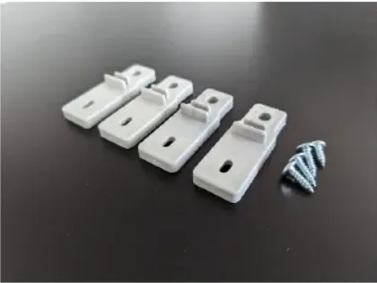
Select the installation location: Choose a suitable location that is easily accessible and offers good network coverage.
Fastening the brackets: Attach the brackets to the housing using the screws supplied as shown.
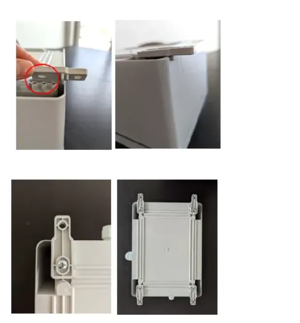
Mounting on the wall Attach the EcoPhi Plant Controller securely to the wall using the four brackets and suitable screws and plugs. Make sure that the housing hangs horizontally to allow easy cabling.
Cable management: Route the cables neatly through the cable grommets provided and secure them with cable ties if necessary to avoid clutter and ensure a secure installation.
3 Controls
The control functions of the EcoPhi Plant Controller are specially tailored to the needs of individual applications and are configured in close coordination with EcoPhi.
This chapter describes the basic aspects of the control units and the optional energy management system (EMS).
3.1 Individual controls
The EcoPhi Plant Controller controls are manufactured individually and are only available on request. This ensures that the controller is precisely matched to the requirements of the respective system. If you are not sure whether a individual controls are available for your application or is part of your system, please contact your dealer or EcoPhi sales agent directly.
Settings of the control parameters:
The control parameters can be configured via the EcoPhi Cloud under the “Action Conditions” section. This functionality enables
- Assignment of control logic: Specify which conditions should trigger certain control actions.
- Data provision: Provide the controller with the necessary data points (e.g. sensor data or operating states).
- Optimize system performance: Monitor and adjust control parameters as needed to ensure optimal performance.
3.2 Energy management system (EMS)
In addition to individual control systems, EcoPhi offers an EMS (energy management system) that has been specially developed for complex applications in the renewable energy sector. The EMS enables the intelligent control and optimization of energy flows, especially in systems with multiple energy sources and consumers.
Commissioning of the EMS:
The EMS may only be commissioned by EcoPhi or a certified partner. This ensures that all configurations are carried out correctly and that the system works reliably.
Correct role assignment:
When setting up the EMS, it is crucial that all devices are created with the correct roles. Roles define which function a device performs in the system (e.g. energy generation, storage or consumption). Incorrect role assignment can lead to errors in the system. A more detailed description of role assignment can be found in the platform manual.
4 Error messages
This chapter describes how you can proceed in the event of errors or problems with the EcoPhi Plant Controller in order to identify and, if necessary, rectify the causes.
LEDs flash red quickly
If all the Plant Controller LEDs flash red quickly, this indicates a hard fault in the software. This is a critical error that puts the device out of operation. In such cases, the following steps should be taken:
Restart the device: Press the Restart button to reset the device. In many cases, this will temporarily rectify the error so that a new connection to the platform can be established.
Contact support: If the error persists, contact EcoPhi Support. Make a note of the exact time of the error and all observed symptoms to enable a quick diagnosis.
Touch screen no longer responds and LEDs S1 and S2 flash monotonously or are off
This behavior indicates a serious internal fault, which is usually caused by GND faults in connected devices. Poor earthing can result in voltage differences between the EcoPhi Plant Controller and the connected devices (e.g. via RS485 or Ethernet) having to be reduced. This can cause internal damage to the Plant Controller. In such cases, the following steps should be taken:
Contact EcoPhi Support: Disconnect the device from the power supply and the connected devices and report the problem to EcoPhi Support. Describe the connected devices and the cabling in order to narrow down the cause of the problem.
Check earthing: Ensure that all connected devices are properly earthed. Poor earthing can lead to voltage differences that are equalized via the communication lines (e.g. RS485 or Ethernet) and can therefore cause damage.
Sensor or externally connected device is not responsive
If a connected sensor or external device does not respond or does not provide any data, proceed as follows:
-
check cable connections: Check that all cables are correctly and firmly connected to the corresponding pins. Also check whether there is any visible damage to the cables, such as breaks or corrosion.
-
check the status on the display: For analog and digital sensors: The status of these sensors is shown live on the Plant Controller display. A signal displayed as “On” or “Off” (for digital sensors) or as a bar (for analog sensors) indicates that the device is correctly wired. If no signal is visible, there may be a wiring error or a defective sensor.
-
check serial connections: RS485 or RS232 connections cannot be checked directly via the display. These connections are diagnosed via the cloud or a debugger on site.
-
RS485 device does not respond: If an RS485 device does not respond to commands, carry out the following steps:
Check Modbus ID: Ensure that the Modbus ID of the connected device is configured correctly.
Check the wiring: Check that cables A and B are connected correctly and are not reversed. Incorrect polarity means that no data can be transmitted.
Termination: Check whether a termination resistor (typically 120 Ohm) has been inserted at the end of the RS485 line. Signal interference can occur without this resistor.
Signal interference: Ensure that the RS485 cable is not routed near high-voltage lines or other sources of electromagnetic interference.
Debugging: Use a debugging tool or a protocol analyzer to check the data traffic on the RS485 line. This can help to identify communication problems.
- settings in the platform: Check in the platform whether the settings for the corresponding sensor are correct (e.g. readout frequency, Modbus port or Modbus TCP port).
If the platform shows the connection to the sensor but the data does not appear correctly, the problem may be with the sensor itself.
5 Support and further information
If you encounter any problems with the EcoPhi Plant Controller during installation, configuration or operation, our support team will be happy to help.
Please create a ticket via our online ticket system: https://ecophi.io/support-request/
Our team will get back to you promptly with a solution or further instructions.
EcoPhi Renewables Engineering GmbH
Alter Schlachthof 33
76131 Karlsruhe
www.ecophi.io