Device Setup: Advanced Box
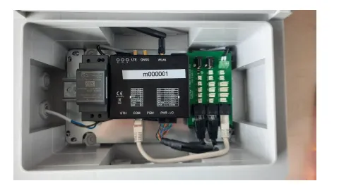
Installation and Setup Manual
Introduction
Before your first installation, we recommend to test the Monitoring Box in your office and with good network connection
Warnings and Instructions

Read the instructions and manual carefully before use.
Caution:
- Electric Shock. The device operates with electrical voltage and carries a risk of electric shock if not used according to the manual
- Disconnect from power source during installation
- Do not modify or alter the device
- Do not operate with damaged cords or plugs
- Turn off and unplug before cleaning or servicing
- Repairs by qualified personnel only
- Use within the specified temperature range
- Keep out of reach of children
- Close the device after successful installation
- Avoid excessive force or rough handling
Notes on correct cabling and connections

80% of all problems are caused by incorrect cabling and connections!
General notes:
- It is strongly recommended to use shielded cables
- Make sure that there are no sources of interference close to the cables, e.g. motor cables, power cables, cables with high power.
- The longer the distances, the stronger the influence of possible sources of interference
- Connect cables professionally and not via loose plug contacts or simple insulating tape.
- Remove the supplied clamps, as they are not intended for permanent use, but only to show the correct wiring.
- Use the supplied heat shrink tubes to extend and connect the cables.
For serial devices:
Avoid star connections, in the case of star connections the maximum distance is 100 m A 120 Ohm resistor at the end of the connections improves the transmission
For pulse sensors:
Avoid magnetic interference fields in the vicinity of pulse sensors, e.g. door sensors or water meters.
1. Short Manual
- Connect with LAN, SIM or Wi-Fi
- Connect the devices and sensors to the EcoPhi Monitoring Box
- Do the online settings
2. Connection Settings
Info: If you have ordered an EcoPhi Box with SIM card service, you can skip this chapter as the Box will automatically connect with the provided SIM card.
There are 3 ways to connect: LAN, SIM and Wi-Fi.
During the first setup, the device should be connected to a LAN connection if the APN or Wi-Fi is not yet set. Due to the connection quality, it is generally recommended to connect the device via LAN during setup.
Depending on the mobile data provider, the SIM needs manual settings. For this, the device should be connected via LAN. If the SIM card works directly, this is not necessary.
To set the Wi-Fi parameters, the device must be already online. For this, a LAN connection is recommended.
2.1 Connection Settings via the EcoPhi Cloud Platform
If you use LAN, you don’t need to do the online settings. Log in to the EcoPhi platform (www.ecophi-monitoring.com) and open the “Device Settings” dashboard.
Info: To be able to make device settings, you need access to the EcoPhi platform and a PIN. If you haven’t received a PIN yet, open the “Request PIN” tab. An email with your PIN will be sent to your email address. Check the Spam, if you haven’t received the mail.
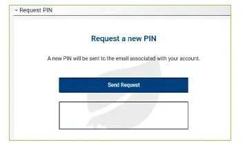
On top of the page under “Device”, select the correct Device ID (the Device ID is printed on the outside of the EcoPhi Box). Nothing needs to be changed under ” Mod IDs”.

The “Device Status” indicates whether the EcoPhi Box is currently connected. “Connection Mode” shows the connection type (LAN, WLAN, SIM).

Under “Data Checkup” you can see when the last time a connection to the EcoPhi Box was established and you can check all transmitted data in the “All values” graph.

Switch to the “Connection Settings” tab.
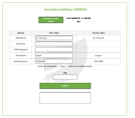
Click on “Request current values” to request the current settings from the Box. A query is sent to the EcoPhi Box, after which the EcoPhi Box sends the current settings. A timer of 10 seconds is set for this.
2.2 LAN Connection
Open the cover of the EcoPhi Box with the attached key. Insert a LAN cable through the open cable channel marked “LAN” of the EcoPhi Box and connect it to the “ETH” port of the data logger. You don’t need to make additional settings for establishing the LAN connection. The box will now automatically establish a connection. If no connection is being established, please restart the device (see instructions below). LED A of the data logger is permanently red when a LAN connection is established. When flashing red, an attempt is being made to establish a connection.
2.3 SIM/ Mobile Data Connection
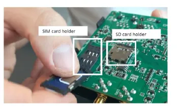
Important! Make sure that the SIM card is topped up with mobile data and that no PIN is required! Open the EcoPhi Box, open the data logger inside and insert the SIM card:
- Take out the cover of the data logger to get access to the circuit board.
- Slide back the metal clip on the SIM card holder and fold it up.
- Insert a local SIM card with internet connection and without a PIN code.
- Close the SIM card holder and fasten the metal clip.
- Put the cover back on the data logger and close the data logger.
Log in to the EcoPhi platform and open the “Device Settings” dashboard.
Very often it’s not required to enter the APN details manually. If you are not sure, you can try it with your SIM card by just inserting the SIM card without changing the APN details. The device might need 20 minutes for the first connection, but entering the APN manually is not always required.
To change the settings online, go to the “Connection Settings” tab and enter the APN data. You can get the APN information online or directly from the mobile data provider.

Confirm the entries with your PIN. The connection settings are not applied until the system is restarted. For a restart, switch to the lower tab “Restart Device”. Confirm the restart with your PIN.
Info: As long as the EcoPhi Box is connected via LAN, this connection is maintained. To check the SIM and Wi-Fi settings, you have to disconnect the LAN connection first. LED A is permanently green when a SIM connection is established. When flashing green, an attempt is being made to establish a connection.
If no connection is being established, restart the device again.
2.4 WLAN/ WIFI Connection
If you want to establish a Wi-Fi connection, the device first has to have a connection via LAN or SIM.
To establish a Wi-Fi connection, enter the Wi-Fi name and the password under the “Connection Settings” tab.
Note: The characters ”;” and "" are not valid and therefore cannot be part of the Wi-Fi password.

Confirm the entries with your PIN.
The connection settings are not applied until the system is restarted. For a restart, switch to the lower tab “Restart Device”. Confirm the restart with your PIN.
Info: As long as the EcoPhi Box is connected via LAN, this connection is maintained. To check the SIM and Wi-Fi settings, you have to disconnect the LAN connection first.
LED A lights up orange continuously when a Wi-Fi connection is established. When flashing orange, an attempt is being made to establish a connection.
3. Preparation of Sensor and Device Cables
EcoPhi provides already prepared and ready-to-use sensors including cables. Depending on whether you have ordered the sensors prepared or not, follow one of the two steps below. Most of the sensors can be installed plug-and-play. Check chapter 4 for specific instructions for some of the sensors.
3.1 Pre-Prepared Sensors
The matching plugs allow you to connect the sensors directly to the EcoPhi Box. The colors and amount of pins make sure you connect the sensors to the right plugs.
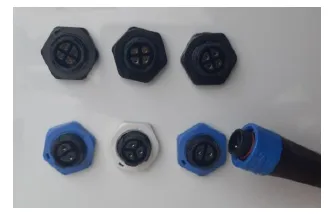
3.2 Not Prepared Sensors
For sensors that are not pre-prepared, the sensor is will be delivered connected in the correct way to an EcoPhi plug via a clamp.
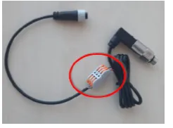
When extending the cables, make sure to follow the order of the colors. You can also refer to the respective sensor data sheets for the correct cabling. Plugs for sensor connection:
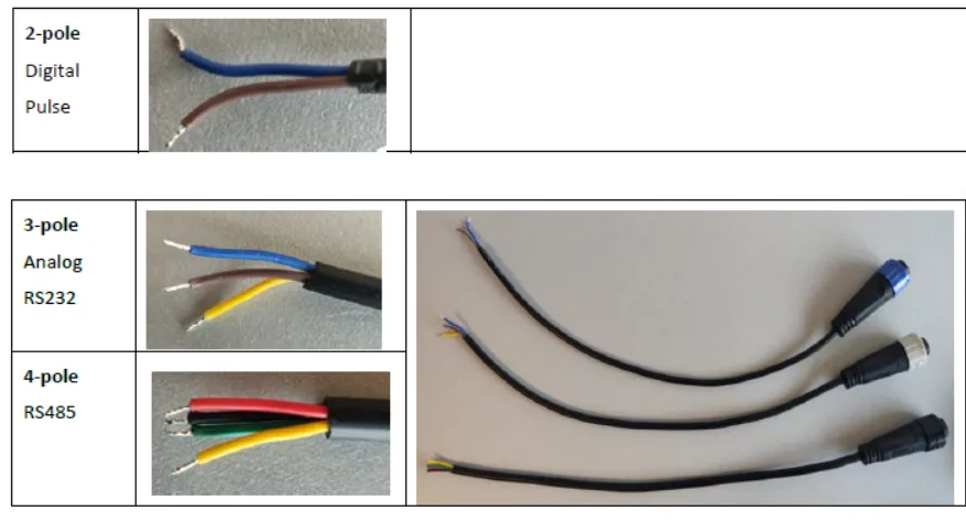
The color coding of the EcoPhi Plugs:
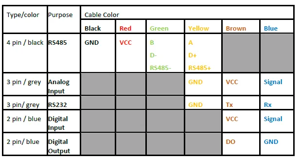
Connect the sensor with the matching plug to the EcoPhi box.

3.3 Additional steps for Distributors
The pin headers of the sensor cables will be connected to the EcoPhi distribution board.
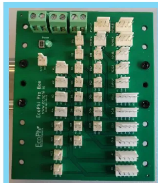
After connecting these to the outside cover of the box, make sure to label the plug accordingly.
3.4 Inverter Connections
There are usually 3 ways to connect an inverter:
- RS485
- RS232
- Ethernet/LAN.
Info: Sometimes, in addition to the cable connection, inverter specific settings and steps need to be taken. For this, please refer to the specific inverter manual or the manufacturer instructions.
RS485 connection (black 4 pin plug) This is the most common way of connecting an inverter. Technically, only two pins are required for this communication (A=yellow and B=green). These 2 pins need to be connected to the inverter (for more information please refer to the individual inverter manual).
The other 2 pins (red and black) are usually used to supply power to RS485 devices which need a power supply. When connecting inverters, they can also be used to supply the EcoPhi Boxes with power from the inverter. For this, the red cable needs to be connected to the positive pole (DC) and the black cable to the GND of the inverter. If the power supply is not used, please cut it safely, since it’s still connected to the power supply of the box. If you want to connect more than one inverter, it is recommended to connect all inverters with A (yellow), B (green) and GND (black) in a so called “daisy chain” from first to the last inverter.
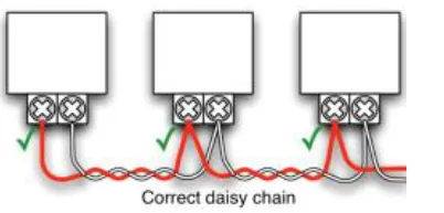
The maximum length of that chain is 1200 meter. Please make sure that the cable is protected from any source of electromagnetic noises.
RS232 connection (grey 3 pin plug) The RS232 connection is usually a connection port for single devices. In some cases, it can connect up to 9 inverters. For that, the inverters need to be connected to each other with additional data cables. The EcoPhi Monitoring Box will only be connected to the main device of the inverters.
For more information, please refer to the individual inverter manual.
Ethernet connection For a connection via Ethernet (usually Modbus TCP), a standard RJ45 cable needs to be connected from the inverter to the EcoPhi Monitoring Box. This cable needs to be connected to the “ETH” port inside the box. If you are using more than one inverter, an Ethernet Switch port must be used, so that all inverters are in one network.
Please also note that the use of the Ethernet connection can be in conflict of using the Ethernet connection to provide internet to the box. As soon as a Modbus TCP protocol is selected in the device setup, the use of internet via Ethernet might be limited.
4. Installation of selected sensors
4.1 AC Current Clamp
Info: Use only in combination with an energy meter.
Place the current clamp around the cable carrying the current to be measured. Always place the current clamp only around the single phase and not around the whole cable, otherwise the return line will also be measured and both currents will cancel each other out.
Place the arrow engraved in the current clamp in the direction of the expected current flow (currents in the other direction are counted negatively).
4.2 AC Current Sensor
Type: Analog Sensor
Clamp the AC current sensor around the cable carrying the current to be measured. Always place the AC current sensor only around the single phase and not around the whole cable, otherwise the return line will also be measured and both currents will cancel each other out.
Place the arrow engraved in the current clamp in the direction of the expected current flow (currents in the other direction are counted negatively).
4.3 DC Voltage Sensor
Type: Analog Sensor
Apply the voltage to be measured to input 8 (+) and input 5 (-). Apply the analog connection:

- VCC to input 1
- GND to input 2
- AIx to input 3
4.4 Door Sensor
Type: Digital sensor
Connect the sensor cable to the digital input (the polarity does not matter).
Attach the fixed sensor end to the door frame and attach the loose sensor end to the door. To fix the sensor, loosen the adhesive strip. Make sure that there are no magnetic interference fields in the immediate vicinity.
The sensor cable must always be at least 10cm away from the nearest power cable, otherwise interference may occur.
4.5 Energy meter SPM91 Single Phase
Type: Serial sensor
Attach phase and neutral input to terminal 1 (phase) and terminal 2 (neutral).
Attach phase and neutral output to terminal 3 (phase) and terminal 4 (neutral).

Attach serial communication to terminal 7 (A) and terminal 8 (B). Note the ID printed on the energy meter for doing the online settings properly (Chapter 5.1).
The sensor cable must always have a distance of at least 10cm to the next power cable, otherwise interference may occur.
4.6 Energy Meter SPM93 3-Phase
Type: Serial sensor
Info: To be used in combination with current clamps.
Attach the neutral input to terminal N of the energy meter. Attach phases 1, 2 and 3 to terminals 1, 3 and 5 of the energy meter. Attach one current clamp (Phase 1): S1 to L1 input and connector S2 to L1 output. Attach one current clamp (Phase 2): S1 to L2 input and connector S2 to L2 output. Attach one current clamp (Phase 3): S1 to L3 input and connector S2 to L3 output.

Attach the serial communication to terminal 16 (A) and terminal 15 (B). GND and VCC are not used. Make sure to isolate the GND and VCC ends.
Note the ID printed on the energy meter for doing the online settings properly (Chapter 5.1).
The sensor cable must always have a distance of at least 10cm to the next power cable, otherwise interference may occur.
4.7 Irradiance Sensor/ Indicator
Type: Analog sensor
Plug the sensor into the analog input of the EcoPhi Box. Extend the cable as needed. Place sensor in sun. For the use in a solar system, install the sensor as close as possible and in parallel to the solar panels. Watch out for possible shadows.
With an irradiance sensor, you can enable the function “Irradiation Analytics”, to compare the possible and actual energy production. Please refer to https://docs.ecophi.de/device_setup/analytics_and_functions/#1-irradiation-analytics for the setup.
4.8 Level Sensor
Type: Analog sensor
Plug the sensor into the analog input of the EcoPhi Box. Extend the cable as needed.
It is important to note that the level sensor has a special cable which supplies the sensor itself with a reference pressure from the atmosphere. This cable must be laid at least up to the ambient pressure (above the water line), otherwise the measurement results will be falsified.
Place the sensor in the water to be measured. The sensor will report how many feet of water is above it. If a water tank is to be measured, then it should be attached to the bottom of the tank. If a borehole is to be measured, then it should be mounted directly above the pump to show how much water is still above the pump. Pay attention to the measuring range. If more water than the measuring range is above the sensor, the maximum value is indicated.
4.9 Pressure Sensor
Type Analog sensor
Plug the sensor into the analog input of the EcoPhi Box. Extend the cable as needed.
The pressure sensor must be installed in a ¼ inch thread. A T-fitting can be used for this purpose.
If the pressure sensor is used for water, make sure that no air bubbles can collect in front of it. Otherwise the measuring results can be falsified.When installing, make sure that the thread is tight.
4.10 Rain Gauge
Type: Digital Sensor
Plug the sensor into the digital input of the EcoPhi Box. Extend the cable as needed.
Place the sensor outdoors so that rain can enter unimpeded.
Be aware of distracting surroundings or possible sources of pollution. Mount the sensor to an even area with screws so that it is level.
The sensor cable must always be at least 10cm away from the nearest power cable, otherwise interference may occur.
4.11 String Monitoring Unit
Type: Serial sensor
Plug the sensor into the Modbus input of the EcoPhi Box. Extend the cable as needed.

Connect the serial communication (A) to terminal CN2.1, (B) to terminal CN2.2, (VCC) to terminal CN1.1 and (GND) to terminal CN1.3. Attach the PV voltage to be measured to CN3 (each at + and -). Put the strings to be measured through terminals CH1..8. Pay attention to the direction of the current. This is marked by an arrow.
Note the ID printed on the energy meter for doing the online settings properly (Chapter 5.1).
The sensor cable must always have a distance of at least 10cm to the next power cable, otherwise interference may occur.
4.12 Temperature and Humidity Sensor - outside
*** Type: Serial sensor***
Plug the sensor into the Modbus input of the EcoPhi Box. Extend the cable as needed.
Place the sensor in the location where temperature and humidity are to be measured.
The sensor is protected against rain, so it can be placed outdoors. Make sure that the sensor is never submerged in water.
Note the ID printed on the energy meter for doing the online settings properly (Chapter 5.1).
The sensor cable must always be at least 10cm away from the nearest power cable, otherwise interference may occur. Dillinger is currently extended with the following plugins. Instructions on how to use them in your own application are linked below.
4.13 Temperature and Humidity Sensor - inside
Type: Serial sensor
Plug the sensor into the Modbus input of the EcoPhi Box. Extend the cable as needed.
Place the sensor in the location where temperature and humidity are to be measured.
The sensor is designed for indoor use and must be protected from rain. Ensure that the sensor is never submerged in water.
Note the ID printed on the energy meter for doing the online settings properly (Chapter 5.1). The sensor cable must always be at least 10cm away from the nearest power cable, otherwise interference may occur.
4.14 Temperature Sensor
Type: Analog sensor
Plug the sensor into the analog input of the EcoPhi Box. Extend the cable as needed.
Place the temperature sensor at the desired location. If the temperature sensor is threaded, screw in at appropriate location and seal it.
4.15 Water Meter
Type: Digital Sensor
Plug the sensor into the digital input of the EcoPhi Box. Extend the cable as needed.
Install the water meter in water circuit and seal it.
Ensure that there are no magnetic interference fields in the immediate vicinity.
The sensor cable must always be at least 10cm away from the nearest power cable, otherwise interference may occur.
5. Setup of Devices and Sensors
5.1 Set up Inverters and other Devices via Serial Interfaces
Note that depending on the inverter and device, settings must be made directly on the connected device. Depending on the inverter, separate instructions are available for this.
Connect the inverter to the monitoring box according to the manufacturer’s instructions or an existing EcoPhi manual.
Make sure that the EcoPhi box is connected to the Internet. Log in to the EcoPhi platform and open the “Device Settings” dashboard.
Switch to the tab “(serial communication)”.
Click on “Request current values” to request the current settings from the device. A request is sent to the EcoPhi Box, whereupon the EcoPhi Box sends the current settings. A timer of 10 seconds is set for this. Depending on the EcoPhi Box and Platform subscription, up to 32 queries can be set. New queries can be added under “Add setting”:
- “Mod ID”: Depending on the inverter or sensor, the ID is predefined. Please refer to the instructions of the inverters/devices. Duplicate IDs are not permitted. If an ID is specified that already exists, the existing query will be overwritten.
- “Readout Time (seconds)”: An individual query interval can be defined for each query. The value is limited depending on the service level.
- “Protocol”: Select the device from the list. If your device does not appear or if you are not sure which protocol to select, contact EcoPhi Support. There are four classes of devices:
— From 1000 to 1999: Inverters and Pump Controllers.
— From 2000 to 2999: Generators.
— From 3000 to 3999: Meters and Sensors.
— From 4000 to 4999: Batteries.
- “IP (if needed)”: An IP must be entered for some devices. Please refer to the instructions of the inverters/devices. (The usage of devices with an IP, might impact the possibility to connect the device via Ethernet)
Confirm the entries with your PIN.
Delete queries: Existing queries can be deleted individually. To do this, select the query to be deleted by clicking on the circle in the last column. The selected column is highlighted in red.
Confirm the deletion of the query with your PIN.
5.2 Connecting Digital and Pulse Sensors
Place the sensor at the final location. Connect the cable to the matching connector at the EcoPhi Box.
Make sure that the EcoPhi box is connected to the Internet.
Log in to the EcoPhi platform and open the “Device Settings” dashboard.
Switch to the “Analog, digital, and pulse sensor settings” tab.
Click on “Request current values” to request the current settings from the device. A request is sent to the EcoPhi Box, whereupon the EcoPhi Box sends the current settings. A timer of 10 seconds is set for this. Settings:
“Readout time (seconds)”: Here you can set the time interval at which the sensors should be read out. The value is limited depending on the service level.
“Units per Counter”: Here you can enter for each pulse sensor how many units are counted per pulse. The information for this can be found directly on the sensor or in the EcoPhi sensor data sheets. If no pulse sensors are connected, nothing needs to be entered. Example: A water meter measures 10 liters per pulse/counter. In this case 10 is entered here. Confirm the entries with your PIN.
Info: The sensor settings are applied directly. A restart of the system is not necessary. Info: At the top of the page under the tab “Data Checkup”, you can check “All values” to see if the sensor values arrive correctly.
5.3 Connecting and setting up Analog Sensors
Place the sensor at the desired location. Connect the cable to the matching connector on the box.
Make sure that the EcoPhi box is connected to the Internet.
Log in to the EcoPhi platform and open the “Device Settings” dashboard.
Switch to the “Analog, digital, and pulse sensor settings” tab.
Click on “Request current values” to request the current settings from the device. A request is sent to the EcoPhi Box, whereupon the EcoPhi Box sends the current settings. A timer of 10 seconds is set for this.
Settings: “Readout time (seconds)”: Here you can set the time interval at which the sensors should be read out. The value is limited depending on the service level.
“Analog …”: Under “Type”, one of three sensor types must be selected. The sensor type can be found in the EcoPhi Sensor Data Sheets or on the label of the sensor. Under “From” and “Till”, the measuring range is entered. The info for this can be found directly on the sensor or in the EcoPhi Sensor Data Sheets.
Info: The sensor settings are applied directly. A restart of the system is not necessary.
Info: At the top of the page under the tab “Data Checkup”, you can check “All values” to see if the sensor values arrive correctly.
5.4 Connecting and setting up Modbus sensors
Place the sensor at the final location. Connect the cable to the matching connector on the EcoPhi Box (4-pin).
Make sure that the EcoPhi box is connected to the Internet.
Log in to the EcoPhi platform and open the “Device Settings” dashboard. Follow the instructions in chapter 5.1 - Connecting inverters and other devices via serial interfaces.
6. Operation
6.1 Check the system operation
To check your system and see the data, log in to the EcoPhi platform. You will find a separate description on the features and option of the EcoPhi platform.
6.2 Retrieve locally stored data via SD card

The SD card is located next to the SIM card. Slide back the metal piece on the card holder. Pull out the SD card. Make sure to put the SD card back in the end.
6.3 Restart the Device
To restart the device, press the button between the GNSS and WLAN antenna ports on the data logger with a small needle or paperclip.
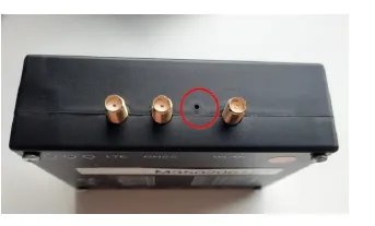
7. Wall Mounting
In the small bag you will find four holders and screws to fix the EcoPhi Box to the wall.
For mounting you also need four more screws with wall plugs.
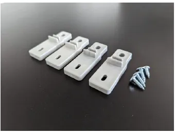
Attach the holders with the included screws to the back of the box.
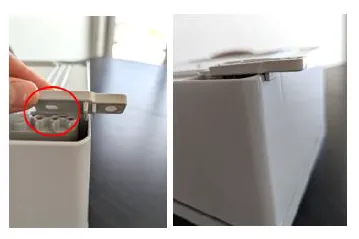
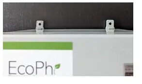
Now you can mount the EcoPhi Box to the wall.
8.Troubleshooting
I have inserted a SIM card but the device doesn’t connect to the cloud Does the SIM card have a PIN? It is important to remove the PIN. If LED A is blinking red several times per second, this is typically a sign for this error.
Does the SIM card have mobile data available? Make sure that you have mobile data.
Make sure that the SIM card is inserted correctly.
Make sure that the antenna is connected correctly and placed at an elevated location. Make sure to remove possible sources of interference.
Make sure you have the correct APN information from your SIM provider.
If possible, try to connect the device to LAN first.
Otherwise you can remove the SIM card and create a mobile hotspot, with name: aveefunky_2,4 and password: funky2015avee2019
Once the device is connected to either LAN or Wi-Fi, make the correct APN settings online (see instructions above).
Restart the device after that. Note that in very rare cases it can take up to 60 minutes for the device to connect for the first time.
The box was running normally and no longer starts It is possible that a short circuit in a defective sensor has shut down the overall power supply of the box.
Turn on the box, remove the sensors one by one to identify the defective sensor.
Digital sensor does not display values
80% of all errors are due to incorrectly connected cables.
Check cabling:
Check connectors especially if cables have been extended.
Look for possible sources of interference near the cable (e.g. motor cables, cables with high power). Make sure there is enough distance to these possible sources of interference.
Check the sensor for damage.
Check if the sensor is in the correct pin location on the EcoPhi board.
Analog sensor does not display values
80% of all errors are due to incorrectly connected cables. Check cabling: Look for possible sources of interference near the cable (e.g. motor cables, cables with high power). Make sure there is enough distance to these possible sources of interference.
Check the sensor for damage. Check that the sensor is connected to the correct pin location on the EcoPhi board.
Plug the sensor connector onto the board, turn on the box and check if 24V voltage is measurable between the brown and yellow wires. Connect another sensor to the same slot and check the values on the dashboard to rule out a defect at the slot.
Serial sensor (Modbus) does not display values
80% of all errors are due to incorrectly connected cables.
Check cabling: Look for possible sources of interference near the cable (e.g. motor cables, cables with high power). Make sure there is enough distance to these possible sources of interference.
Check the sensor for damage. Check that the sensor is connected to the correct pin location on the EcoPhi board. Check the Device Setup Dashboard to see which protocol is currently set and select the correct protocol. Check that the ID of the inverter matches the settings in the dashboard.
Inverter values are not displayed
Check that the cable is connected correctly and that it is connected to the correct port of the inverter (names vary depending on the manufacturer and are sometimes confusing). Check if the end of the cable is connected to the correct EcoPhi slot. Check the Device Setup Dashboard to see which protocol is currently set and select the correct protocol. Check that the ID of the inverter matches the settings in the dashboard. Check if the settings on the inverter have been made correctly.
Analog sensor values are not correct
Check the cable for correct connection. Check in the Device Setup Dashboard in the settings if the correct range is set.
See if the measuring range matches the sensor or is below / above the possible measuring range.
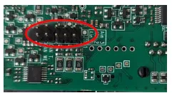
If multiple sensors are connected, remove all other sensors and check in the dashboard if values are still displayed. If values are displayed even though no sensor is connected, the Voltage and Current settings are probably reversed. In the data logger, you must set whether a Voltage and Current signal is used. On the Advanced Box, all three analog inputs are set to 4-20mA by default. To change an input to 0-10V, the data logger must be opened and the respective jumper (Ain 1-3) removed.
Pulse sensor values are not correct
Check the multiplier which is set in the Device Setup Dashboard and adjust the parameter.
The inverter has problems when the EcoPhi box is connected
This can happen, when the EcoPhi box is powered by the inverter and is possibly because it is supplied directly from the board as the box consumes too much current and this disturbs the inverter. In this case, use external power supply, if available. Otherwise you need to integrate a power backup solution.
9.EcoPhi Support
The device ID is printed outside of the box (the ID starts with “m…”). Make sure you provide this number when you contact the EcoPhi support. In case you have difficulties setting up your EcoPhi Monitoring Box, we are here to help you. Please contact the EcoPhi support under support@ecophi.de or contact your support agent at EcoPhi.